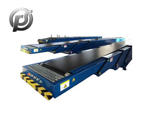
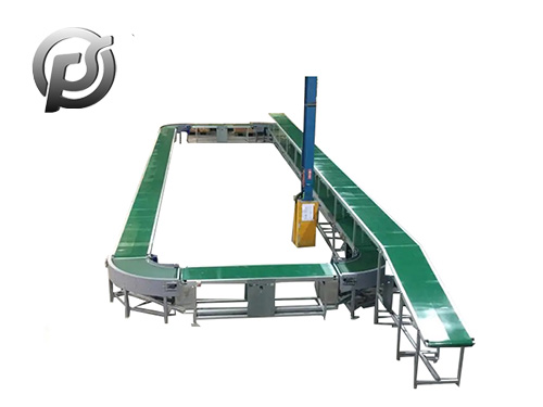
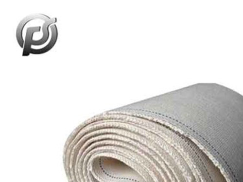
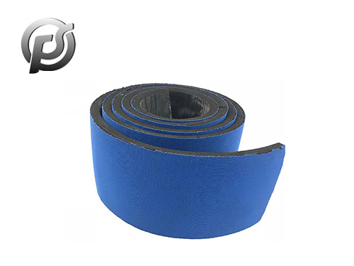
Belt conveyor transmission device: refers to the prime mover movement and power to the working mechanism of the intermediate device.
Belt conveyor transmission device structure is mainly composed of head transmission device, belt storage device, tape collection and release device, etc. :
First, the head transmission device
The head transmission device is composed of a driving drum, a reducer, a hydraulic coupling, a frame, a unloading drum and a cleaner.
The two motors transmit the pitch to the two driving drums through the hydraulic coupling and the reducer respectively (two gears can also be driven in series).When the gears are driven, The hydraulic coupling is YL-400 type, which is composed of pump wheel, turbine, casing, driven shaft, The hydraulic coupling is YL-400 type, which is composed of pump wheel, turbine, casing, driven shaft, etc. It is characterized in that there is an auxiliary chamber on the side of the pump wheel. After the motor is started, the liquid flow enters the working chamber through a small hole , to make the load start more balanced, the motor starts close to the hard load, add 20 mechanical oil to the casing, and the oil injection volume is 14m3, the reducer adopts upper gear reduction, the first stage is a bevel gear, the second and third stages are helical gears and spur gears, the total transmission ratio 25.564, the second and third stages are helical gears and spur gears, the total transmission ratio 25.564, the SGW-620/40T scraper conveyor can be universally interchanged, and the reducer and the frame are directly connected by bolts.
The driving drum is welded structure, the outer diameter is Φ500 mm, the surface of the drum has a special vulcanized rubber layer, so to improve the friction between the belt and the drum, prevent slipping, reduce the initial tension, has a good effect.
The unloading end, the head cleaner and the belt type check are easy to unload. The front part of the nose is provided with an overstretched unloading arm, which is composed of a unloading roller and an outstretched frame. The idler roller is installed on the extension frame, and its axis position can be adjusted through the bolts on both sides of the bearing to adjust the deviation of the machine head belt., the lower part of the unloading drum is equipped with two cleaners. Because the scraper of the cleaner is pressed tightly on the rubber belt, it can remove the broken coal adhering to the machine.
The frame is of welded structure and assembled with bolts. All parts of the head transmission device are installed on the frame; The motor and reducer can be installed on the left or right side of the frame according to specific conditions.
Two, tape storage device
Belt storage device includes belt storage bogie, belt storage warehouse frame, reversing drum, roller trolley, traveling trolley, tensioning device, tensioning winch, etc.
The framework of the belt storage device is made of the frame and bracket connected by bolts. Three fixed reversing drums are installed on the two rotating frames of the head transmission device and two reversing drums on the traveling trolley together for the tape to guide the reciprocating in the belt storage device. Shelves are mounted on fixed grooved and flat rollers to support the belt. There is a track on the inside of the shelf for the roller car and the walking car.
The fixed reversing roller is a fixed shaft type, which is used as the main bearing tape when the tape storage device is used to store the tape, so that its overhang is not too large. The dolly dolly needs to be pulled out or returned by manpower when the position of the dolly changes.
The travelling trolley is composed of a frame, reversing drum, block, wheel, etc. The pulley assembly fits into another piece behind the body, positioned so that the body won't lift when stressed. In this way, it is better to maintain the stability of the body and prevent the tape on the reversing drum from running off. The lower part of the body is also equipped with a climbing hook to prevent the wheel from derailing and falling off the road.
When the traveling car moves to the left, the belt is released and the fuselage is extended. When the traveling car moves to the right, the belt is stored and the fuselage is shortened. The belt can be properly tensioner by tightening the traveling car through the wire rope.
At the rear of the belt storage unit, there is a tensioning winch, a belt tension indicator and a tension buffer. The role of the tension buffer is to make the conveyor (when starting the belt always maintain a certain tension, in order to reduce the unappropriateness of the no-load belt and belt between layers of beating).
Three, collect and put the belt device
The retracting and releasing belt device is located at the rear of the tensioning winch, which is composed of a frame, aligning roller, reducer, motor, rotating rod and so on. Its function is to add the belt to the belt conveyor body or remove it from the body of the belt conveyor. Both ends and rear ends of the frame are equipped with a rotating rod, which is used to clamp the main belt when the belt is increased or reduced. When working, one end of the drum is pushed into the frame with the tail frame, and the other end is on the top of the shaft of the reducer. The motor drives the drum through the dial of the shaft of the reducer, reels the tape and releases the tape. When the tape is released, the motor is not turned on by dragging the drum to reverse, and the movable rail can be hung on the frame with the latch to reduce the width. The lifting device should be set above the movable rail to suspend the drum, and the width of the roadway should be widened appropriately according to the specific situation, so as to facilitate the operation of the belt income.
Some belt conveyor transmission installation and debugging requirements
1, belt conveyor leg, column or platform with chemical anchor bolt firmly fixed on the ground;
2. The mounting bolts of all components on the frame should be fully fastened. Each roller should rotate flexibly. The axis line of the supporting roller shaft, the driving drum and the reversing drum shall be perpendicular to the longitudinal center line of the frame;
3, screw tensioning stroke is 1% ~ 1.5% of the captain;
4. The rope switch is installed on one side of the belt conveyor, and the two switches are connected with plastic steel wire rope, with moderate tightness;
5. The deviation switch is installed on both sides of the head and tail of the belt conveyor in pairs. The vertical roll of the switch is perpendicular to the belt edge of the conveyor belt, and ensure that the belt edge is located at 1/3 of the height of the vertical roll. The distance between the vertical roller and the conveyor belt edge is 50 ~ 70mm;
6. The rubber scraper of each cleaner and guide groove should be in complete contact with the conveyor belt; otherwise, adjust the installation bolts of the cleaner and guide groove to make the scraper in contact with the conveyor belt;
7, no load test run after the installation is correct, the test run time is not less than 2 hours, and the following checks:
a. Each roller should be in contact with the conveyor belt and rotate flexibly;
b. No oil leakage in each lubrication area;
c. Each fastener is not loose;
d. Bearing temperature rise shall not exceed 40°C, and the highest temperature shall not exceed 80°C;
e. During normal operation, the belt conveyor should run smoothly without deviation and abnormal noise.
 Custom Conveyor Belts: Enhancing Efficiency and Productivity
 Stone Belt Conveyor: Efficient Material Handling Solution for Mining and Construction
 Exploring the Dynamics of Conveyor Belt Manufacturing in China
 PE Conveyor Belts: Characteristics, Applications, and Advantages